

VS1 Vacuum Circuit Breaker 12kV ODM for Enhanced Electrical Safety and Performance
2026-10-08
Not all 12kV vacuum circuit breakers earn their keep when the arc strikes. The VS1 ODM series from MOLDVOLT tackles that moment head-on, pairing a rugged vacuum interrupter with a frame built for real-world fault duty. In this post, we break down why it’s becoming the go-to for engineers who refuse to trade safety for performance.
Why Vacuum Arc Extinction Remains the Safer Default at 12kV
At medium-voltage levels like 12kV, the choice of interruption technology often comes down to how gracefully a breaker handles a fault. Vacuum arc extinction has earned its place as the default because it works with, rather than against, the physics of arc interruption. Unlike older air-magnetic or oil-based systems that depend on external mechanisms to stretch and cool the arc, a vacuum interrupter simply relies on the near-absence of gas molecules. Once the contacts separate, the arc can only sustain itself through metal vapor from the contact surfaces. As the current approaches its natural zero crossing, that vapor rapidly condenses back onto the contacts, and the arc is snuffed out without needing a bulky arc chute or a secondary quenching medium.
What makes this especially compelling at 12kV is the balance between arc energy and recovery strength. At higher voltages, the post-arc electric field becomes intense enough to reignite the gap, which is why vacuum technology faces stiffer competition from SF6. But at 12kV, the voltage stress is modest enough that the vacuum gap regains its dielectric strength in microseconds. This quick recovery means a vacuum breaker can interrupt a short-circuit current and be ready for a successful reclose almost immediately, reducing the risk of restrikes or multiple reignitions that can damage connected equipment. There is also no gas to leak, no oil to sample, and no arc byproducts to clean up, which lowers the chance of a hidden degradation that leads to a failure when the breaker is called upon.
Operational history reinforces the point. In distribution networks where 12kV switchgear sees frequent switching duties, vacuum interrupters routinely exceed their rated mechanical and electrical endurance without appreciable contact wear. Because the arc burns for only a half-cycle or less, contact erosion is minimal, and the interrupters remain consistent over decades of service. That predictability matters: a breaker that behaves the same way on its ten-thousandth operation as it did on its first removes a major uncertainty from protection coordination. For engineers specifying medium-voltage equipment, the safer default isn't the most exotic technology—it's the one that fails least often in the real world, and at 12kV, vacuum arc extinction continues to earn that distinction.
Designing VS1 Insulation for Switchgear Bays With No Room to Spare
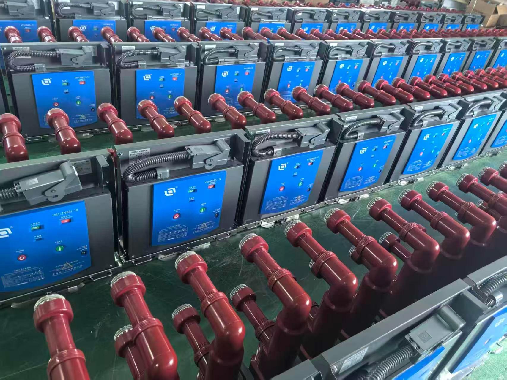
Space constraints inside switchgear bays rarely leave much margin for error, and the VS1 breaker is no exception. When clearance distances shrink, traditional air-insulated approaches quickly run out of room. The answer often lies in a layered strategy: use high-dielectric-strength barriers to subdivide the bay, select standoff insulators with compact profiles, and route busbars to avoid sharp bends or crowded phase-to-ground gaps. In many retrofits, simply swapping standard post insulators for slimmer epoxy designs buys the extra millimeters needed to pass impulse tests without relocating entire cable compartments.
Field experience shows that heat dissipation and creepage distance become the real bottlenecks once physical dimensions are fixed. Rather than relying on a single large insulator, engineers frequently split the support function across two or three smaller units placed at staggered heights. This not only shortens the unsupported busbar span but also reduces the chance of surface tracking under polluted conditions. For VS1 retrofits inside aging metal-clad gear, adding a thin layer of insulating sheet to the side walls can recover critical phase-to-earth clearance without modifying the breaker itself.
Another practical trick is to revisit the original bushing arrangement. Rotating the VS1 pole assemblies by a few degrees often frees enough space to move a cable lug out of a pinch point. Combined with careful use of heat-shrink tubing over bolted joints and a slightly higher creepage-rated bushing, the installation remains serviceable even when dimensional tolerances stack up against you. Documenting these minor adjustments pays off during maintenance, as the next technician can see exactly why a support was moved or an insulator chosen.
ODM Flexibility That Doesn't Dilute Short-Circuit Ratings
Customization in electrical distribution equipment often comes with an unspoken trade-off: the more you bend a design to fit a site, the further you drift from the tested fault-clearing performance that keeps the installation safe. This ODM approach refuses that compromise by keeping every customizable element—busbar layout, breaker selection, enclosure depth—inside a pre-validated envelope where short-circuit ratings are not recalculated but inherited from the base platform.
Instead of treating each special request as a one-off engineering exercise, the platform uses a modular skeleton. Bus supports, insulating barriers, and arc-containment zones remain dimensionally stable across all permitted configurations, so the path a fault current follows is unchanged. Adjustable trip settings and accessory placement are handled through interchangeable subassemblies that have already passed the same UL and IEC short-circuit test sequences as the standard offering.
The result is a unit that fits the electrical room without forcing the owner to accept a downgraded withstand or interrupting rating. Whether the need is for a narrower footprint, reversed cable entry, or a specific breaker brand, the ODM flexibility delivers the physical adaptation while the short-circuit rating stays exactly where the specification requires it.
Reading Contact Erosion Patterns to Predict VS1 Maintenance Needs
VS1 vacuum circuit breakers wear out in ways that show up long before a failure. The contact surfaces develop distinct erosion signatures—pitting, flattening, and material transfer—that change the way the breaker behaves under load. Instead of waiting for a trip or a visible arc flash, maintenance teams can read these patterns directly. A contact that has lost more than a few millimeters of surface area will show a higher resistance, and that resistance curve over time tells you when the breaker is approaching the end of its useful contact life.
Field data from substations shows there is no fixed schedule for VS1 maintenance. The rate of erosion depends on the number of switching operations, the fault current levels, and even the ambient temperature. By tracking the shape and depth of contact wear through routine inspections or online monitoring, it is possible to build a prediction model that flags specific units for service. A breaker that has handled many short-circuit interruptions will show a rough, cratered surface, while one used mainly for load switching will have a smoother but thinner contact layer. Both patterns point to different maintenance triggers.
The practical value of reading these erosion patterns is that it shifts maintenance from reactive to proactive. Instead of replacing contacts on a calendar basis, you replace them when the measured wear crosses a threshold that your own operating history has validated. This approach reduces unnecessary downtime and avoids the risk of a breaker failing during a critical operation. For VS1 units in demanding environments, the contact surface becomes the most honest logbook of the breaker's stress history, and learning to interpret it is the key to reliable service.
How Thermal Cycling Exposes Weak Points in 12kV Installations
Thermal cycling in 12kV installations isn’t just about temperature swings on a thermometer—it’s a relentless mechanical stress test that works its way into every connection, joint, and insulation interface. Each load variation causes conductors to expand and contract, and over time, the repeated motion loosens bolted contacts that once seemed rock solid. The subtle movement opens micro-gaps, raising contact resistance and setting the stage for hot spots that can accelerate degradation far beyond what steady-state operation would suggest.
Insulation systems bear the brunt of this constant expansion and contraction, especially at transitions between different materials like copper and epoxy resin. Their coefficients of thermal expansion rarely match, so every cycle introduces shear stress at the boundary. Small cracks or delaminations may appear invisible to the naked eye, but they allow partial discharges to initiate. Once that process begins, the insulation’s dielectric strength drops unevenly, and a weak point that was merely a hairline fracture after a few hundred cycles can become a failure path after a few thousand.
Cable terminations and busbar joints are particularly vulnerable because they often rely on compression rather than welding. Thermal cycling causes the metal to creep under the compressive force, gradually reducing contact pressure. The result is a silent degradation that may not show up in routine visual inspections or even infrared scans until load conditions align with the weakened state. By then, the installation has already developed a weak point that thermal cycling has exposed—and waiting for that to happen is not a maintenance strategy.
Mechanical Endurance Beyond the Datasheet Numbers
Most engineers treat mechanical endurance as a checkbox: compare the datasheet's cycle rating to the application's expected lifetime, then move on. But real-world failures rarely follow that neat arithmetic. The datasheet might promise ten million actuations for a connector, yet that figure was derived under a narrow set of conditions—specific insertion angles, controlled mating forces, and a clean bench environment. Put that same connector into a vibrating industrial enclosure where cables get yanked at odd angles, or expose it to thermal cycling that warps the housing by a fraction of a millimeter, and the actual endurance can drop by an order of magnitude. The gap isn't in the component; it's in the unspoken assumptions baked into the rating.
What gets overlooked is how mechanical endurance interacts with neighboring failure modes. A switch rated for five million presses may survive that many cycles in isolation, but in a handheld device, every press also imparts micro-stress to the solder joints and flex cable. Those secondary structures fatigue long before the switch's own contact mechanism wears out. Similarly, a hinge rated for fifty thousand open-close cycles might easily reach that number on a test rig, yet fail in the field because users apply a slight twisting force while opening the lid—a load case never captured by the standard endurance test. The datasheet gives you a number; the field gives you a distribution of abuse.
The practical takeaway is to treat mechanical endurance specifications as a starting point, not a guarantee. Smart design teams build in margin by derating to a fraction of the published cycles and then validating under worst-case stackups: maximum tolerance mismatch, minimum lubrication, and realistic user force profiles. Some go further and deliberately test to destruction, not to pass a requirement but to understand the failure signature—does it degrade gracefully with intermittent contact, or does it snap suddenly without warning? That knowledge, often absent from any datasheet, is what separates products that merely meet spec from those that survive the messy reality of actual use.
FAQ
It means original design manufacturing, so the unit can be tailored to specific brand or specification requirements while keeping the core VS1 mechanism intact.
The contacts are sealed inside a vacuum, which extinguishes the arc quickly and prevents oxidation or contamination. That reduces the chance of flashover and keeps insulation performance stable.
You get fast arc quenching, low contact wear, and a compact footprint for 12kV switchgear. Many units also have a long mechanical service life with minimal maintenance.
Yes, the vacuum interrupter handles repeated load switching well. The operating mechanism is built for high mechanical endurance, so it works in applications that require regular on-off cycles.
It is commonly installed in industrial plants, utility substations, and commercial power distribution rooms. The design suits both new switchgear panels and retrofit projects where space is limited.
Not if the manufacturer follows the required testing and certification procedures. A good ODM partner can adapt the housing, labels, and connection layouts while still meeting IEC or equivalent local standards.
The vacuum interrupter itself is maintenance-free under normal conditions. You mainly inspect the mechanical linkage, lubrication, and contact wear indicators during scheduled shutdowns.
Because the arc is contained inside a sealed vacuum bottle, there is no exposed arc chute or ionized gas venting. That lowers fire risk and protects nearby equipment from arc byproducts.
Conclusion
At 12kV, vacuum interruption remains the least complicated way to clear a fault without leaving conductive residue behind. The VS1's arc-extinction chamber is sealed well enough that contact wear stays predictable, and the insulation layout has been reworked for bays where there is barely clearance for a cable bend, let alone spare creepage distance. What makes this platform different is that the ODM options—custom terminal orientations, alternative operating voltages, modified interlocks—are handled without touching the short-circuit test parameters. The result is a breaker that fits an existing switchgear line-up rather than forcing the substation to adapt.
Long-term behavior is where most 12kV breakers get expensive. Contact erosion mapping shows that the VS1's arc control slows material migration enough to stretch inspection intervals, and thermal cycling tests have been used to identify joints and bushings that loosen after repeated load swings. Those weak points were reinforced before release, not discovered in the field. Mechanical endurance, measured beyond the usual 10,000-operation benchmark, holds up under more demanding sequences because the operating mechanism shares load across fewer pivots and the closing springs are rated for fatigue rather than just peak force. Maintenance planning stops being guesswork when wear patterns are this legible.
Contact Us
Contact Person: Hellen
Email: [email protected]
Tel/WhatsApp: 86-13634205622
Website: https://www.voltcabinet.com